
MGCP (RFC 2705) est un protocole client/serveur qui permet au call manager de connaitre et contrôler un port spécifique de la passerelle. Cela permet donc aussi la centralisation de l'administration des passerelles et de toute la gestion du dial plan.
Les commandes sont tranportées au UDP 2427 entre l'environnement call manager et les passerelles.
L'implémentation de MGCP vient avec un concept de PRI Backhaul permettant au call manager de controler le signalisation data Q.931 utilisé sur le port PRI de la passerelle.
Étapes de configurations:
1 - Vérification du matériel:
HQ#show inventory
NAME: "chassis", DESCR: "2801 chassis"
PID: CISCO2801 , VID: V01 , SN: FCZ093311XV
NAME: "motherboard", DESCR: "C2801 Motherboard with 2 Fast Ethernet"
PID: CISCO2801 , VID: V01 , SN: FOC092624PU
NAME: "WIC/VIC/HWIC 1", DESCR: "WAN Interface Card - Serial (1T)"
PID: WIC-1T= , VID: 1.0, SN: 13852239
NAME: "WIC/VIC 2", DESCR: "One port T1 voice interface daughtercard"
PID: VWIC-1MFT-T1= , VID: 1.0, SN: 32255346
NAME: "WIC/VIC/HWIC 3", DESCR: "WAN Interface Card - Serial (1T)"
PID: WIC-1T= , VID: 1.0, SN: 19220982
NAME: "PVDM 0", DESCR: "PVDMII DSP SIMM with three DSPs"
PID: PVDM2-48 , VID: V01 , SN: FOC101317R0
NAME: "PVDM 1", DESCR: "PVDMII DSP SIMM with one DSP with half channel capcity"
PID: PVDM2-8 , VID: NA , SN: FOC0946011N
2- Activation du port T1
card type t1 0 2
3- Configuration horloge
HQ(config)#network-clock-participate wic 2
HQ#show network-clocks
Network Clock Configuration
---------------------------
Priority Clock Source Clock State Clock Type
11 Backplane GOOD PLL
Current Primary Clock Source
---------------------------
Priority Clock Source Clock State Clock Type
11 Backplane GOOD PLL
HQ(config)#network-clock-select 1 t1 0/2/0
HQ#show controllers t1 0/2/0
T1 0/2/0 is up.
Applique type is Channelized T1
Cablelength is long gain36 0db
No alarms detected.
alarm-trigger is not set
Soaking time: 3, Clearance time: 10
AIS State:Clear LOS State:Clear LOF State:Clear
Version info Firmware: 20090113, FPGA: 20, spm_count = 0
Framing is ESF, Line Code is B8ZS, Clock Source is Line.
CRC Threshold is 320. Reported from firmware is 320.
Data in current interval (3 seconds elapsed):
0 Line Code Violations, 0 Path Code Violations
0 Slip Secs, 0 Fr Loss Secs, 0 Line Err Secs, 0 Degraded Mins
0 Errored Secs, 0 Bursty Err Secs, 0 Severely Err Secs, 0 Unavail Secs
HQ#show network-clocks
Network Clock Configuration
---------------------------
Priority Clock Source Clock State Clock Type
1 T1 0/2/0 GOOD T1
11 Backplane GOOD PLL
Current Primary Clock Source
---------------------------
Priority Clock Source Clock State Clock Type
1 T1 0/2/0 GOOD T1
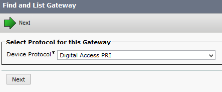
4- Définir le global switch type:
HQ(config)#isdn switch-type primary-ni
5- Configuration du controleur T1, les commandes vont automatiquement générer l'interface série et le port voix pour être utilisé pour la signalisation ISDN D-Channel.
HQ(config)#controller t1 0/2/0
HQ(config-controller)#pri-group timeslots 1-3 service mgcp
HQ#show run interface serial 0/2/0:23
Building configuration...
Current configuration : 138 bytes
!
interface Serial0/2/0:23
no ip address
encapsulation hdlc
isdn switch-type primary-ni
isdn incoming-voice voice
no cdp enable
end
HQ#show run | sec voice-port
voice-port 0/2/0:23
6- Configuration Backhaul:
La configuration va permettre que la signalisation Q.931 normalement recu par le routeur soit transféré directement au CUCM.
HQ(config)#interface serial 0/2/0:23
HQ(config-if)#isdn bind-l3 ccm-manager
7- Configuration MGCP sur le routeur:
HQ(config)#mgcp call-agent 10.10.13.12 //HQ CUCM subcriber
HQ(config)#ccm-manager mgcp //Activation "Call Manager Application" pour mgcp
HQ(config)#mgcp // activation mgcp sur le routeur
HQ#show ccm-manager
MGCP Domain Name: HQ.nissarte.ca
Priority Status Host
============================================================
Primary Registering with CM 10.10.13.12
First Backup None
Second Backup None
Current active Call Manager: None
Backhaul/Redundant link port: 2428
Failover Interval: 30 seconds
Keepalive Interval: 15 seconds
HQ#show isdn status
Global ISDN Switchtype = primary-ni
%Q.931 is backhauled to CCM MANAGER 0x0003 on DSL 0. Layer 3 output may not appl
y
ISDN Serial0/2/0:23 interface
dsl 0, interface ISDN Switchtype = primary-ni
L2 Protocol = Q.921 0x0000 L3 Protocol(s) = CCM MANAGER 0x0003
Layer 1 Status:
ACTIVE
Layer 2 Status:
TEI = 0, Ces = 1, SAPI = 0, State = TEI_ASSIGNED
Layer 3 Status:
0 Active Layer 3 Call(s)
Active dsl 0 CCBs = 0
The Free Channel Mask: 0x80000007
Number of L2 Discards = 0, L2 Session ID = 1
Total Allocated ISDN CCBs = 0
La partie Layer 2 du PRI étant géré directement par le CUCM, le routeur n'étant pas encore déclaré dans la configuration, le statut actuel est TEI_ASSIGNED puisque aucune frames Layer 2 n'est échangé avec mon routeur PSTN.
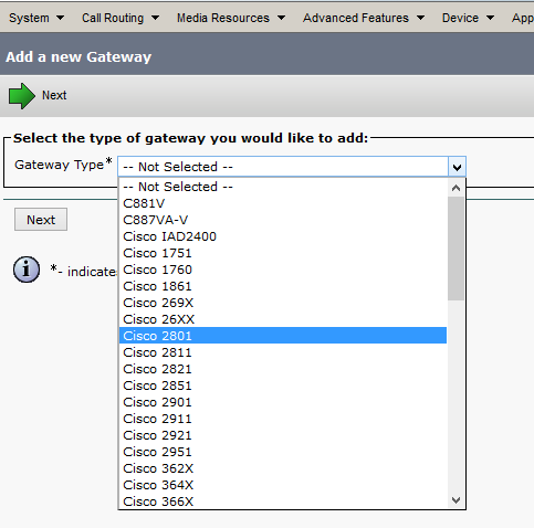
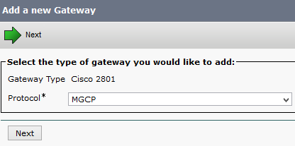
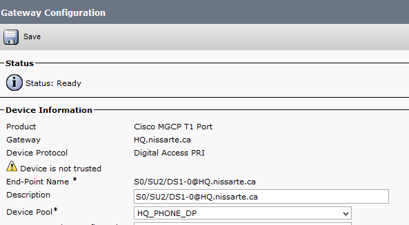
8- Configuration Cisco Call Manager:
Device- Gateway:
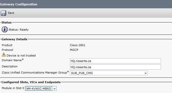
Vérification du nom du routeur:
HQ#SHOW CCM-manager
MGCP Domain Name: HQ.nissarte.ca
9- Redondance: Ajout du CUCM Publisher en tant que backup:
HQ(config)#ccm-manager redundant-host 10.10.13.11
Vérification:
HQ#show ccm-manager
MGCP Domain Name: HQ.nissarte.ca
Priority Status Host
============================================================
Primary Registered 10.10.13.12
First Backup Backup Ready 10.10.13.11
Second Backup None
Current active Call Manager: 10.10.13.12
Backhaul/Redundant link port: 2428
Failover Interval: 30 seconds
HQ#show isdn status
Global ISDN Switchtype = primary-ni
%Q.931 is backhauled to CCM MANAGER 0x0003 on DSL 0. Layer 3 output may not appl
y
ISDN Serial0/2/0:23 interface
dsl 0, interface ISDN Switchtype = primary-ni
L2 Protocol = Q.921 0x0000 L3 Protocol(s) = CCM MANAGER 0x0003
Layer 1 Status:
ACTIVE
Layer 2 Status:
TEI = 0, Ces = 1, SAPI = 0, State = MULTIPLE_FRAME_ESTABLISHED
Layer 3 Status:
0 Active Layer 3 Call(s)
Active dsl 0 CCBs = 0
The Free Channel Mask: 0x80000007
Number of L2 Discards = 0, L2 Session ID = 1
Total Allocated ISDN CCBs = 0